Basic Requirements
Our drivetrain needs to provide sufficient torque to move the brick. The brick weighs 10 lbs, which is equal to 4.5kg. Using an estimate of a coefficient of static friction of 0.2, the force needed to cause the brick to start moving is F = 4.5kg*9.8m/s/s*0.2 = 8.82 N. In order to ensure a margin of error, this number was assumed to be 10 N for further calculations.
Torque T = F*r where r is the radius of a rotating element. This can be rearranged as F = T/r. From this equation it is clear that in order to increase the force output of our robot, we want to minimize the radius of our wheels. The speed of our robot, however is proportional to the radius of our wheels (v = omega r), therefore, for more speed, we want larger wheels. A wheel radius of 1.5 in (38 mm) was selected as a good compromise. Using this number, the torque required is T = 10N*.038m = .38Nm.
Torque T = F*r where r is the radius of a rotating element. This can be rearranged as F = T/r. From this equation it is clear that in order to increase the force output of our robot, we want to minimize the radius of our wheels. The speed of our robot, however is proportional to the radius of our wheels (v = omega r), therefore, for more speed, we want larger wheels. A wheel radius of 1.5 in (38 mm) was selected as a good compromise. Using this number, the torque required is T = 10N*.038m = .38Nm.
Selected Components
Several motors were located in the TA closet and tested to determine which appeared to offer sufficient torque. The best candidate was a Merkle-Korff Industries S1627B. Unfortunately there was no manufacturer data sheet available. In order to determine the performance specifications the armature resistance of the motor was measured using a digital multi-meter (approximately 10 ohms) and a no-load speed was measured while supplying the motor with 5V DC (measured to be about 180 rpm). From these measurements we estimated torque constant to be approximately 0.45 Nm/amp.
Given our assumptions of the necessary torque to push the brick, and the voltage available (approximately 14 V from our two 7 volt batteries), we decided that to implement a motor driving circuit that was capable of handling at least 1 amp of current, and at time closer to 1.5 amps. Of the drivers available in the lab, the L298 was selected as the best fit.
Given our assumptions of the necessary torque to push the brick, and the voltage available (approximately 14 V from our two 7 volt batteries), we decided that to implement a motor driving circuit that was capable of handling at least 1 amp of current, and at time closer to 1.5 amps. Of the drivers available in the lab, the L298 was selected as the best fit.
Motor Driver Circuit
Separate connectors provide access to the logic-level inputs, H-bridge output connections, and the IC’s power supply. The module makes use of a 74HC14 to simplify the drive logic by reducing it to two inputs per H-bridge: direction and enable. Clamping diodes are included on the module PCB to protect the circuit from inductive kickback.
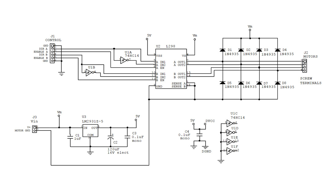
ME118 L298 Dual 2A H-Bridge Schematic
J1 provides the logic-inputs for the motor driver. Each Channel (A or B) has a direction input and an enable input. J2 provides output to each of the motors. J3 provides power to the board, ranging from +5.6V to +18V. The L298 module includes its own voltage regulation, meaning it does not require an externally regulated +5V power supply.
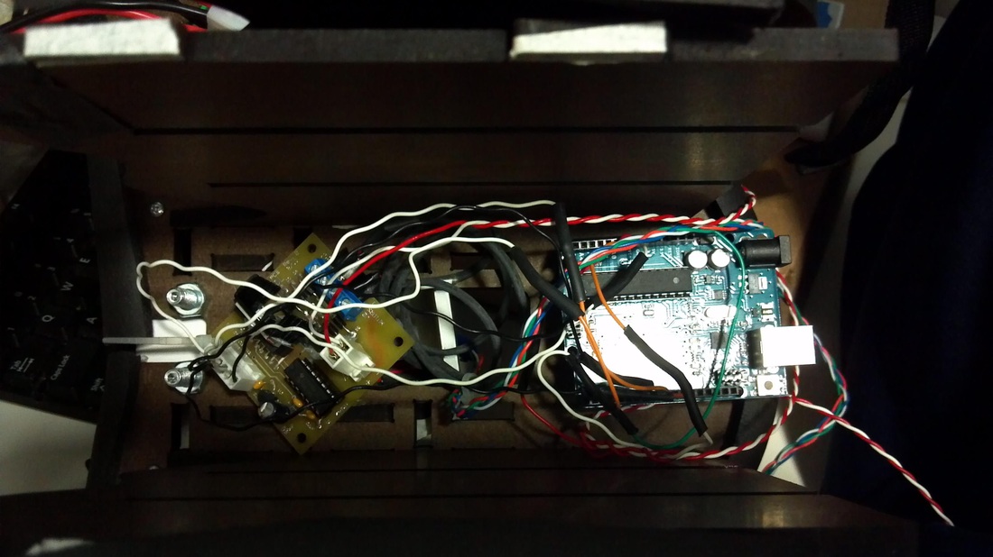
The motor driver boeard can be seen on the left of the image below.
The motor driver boeard can be seen on the left of the image below.
Software
In order to test our motors, simple motor driving functions were written. A file containing these functions is included below.
| Motor Driver Functions for Arduino |
Wheels
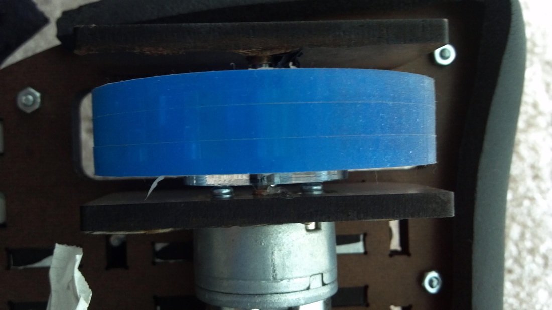
Since the playing surface was very smooth we decided to cast our own wheels out of silicone. A hub and molds were designed in SolidWorks and files generated to cut acyrlic on the laser cutters in the PRL in order to make them (files attached below).
| wheel.sldprt |
| wheel_drawing.ai |
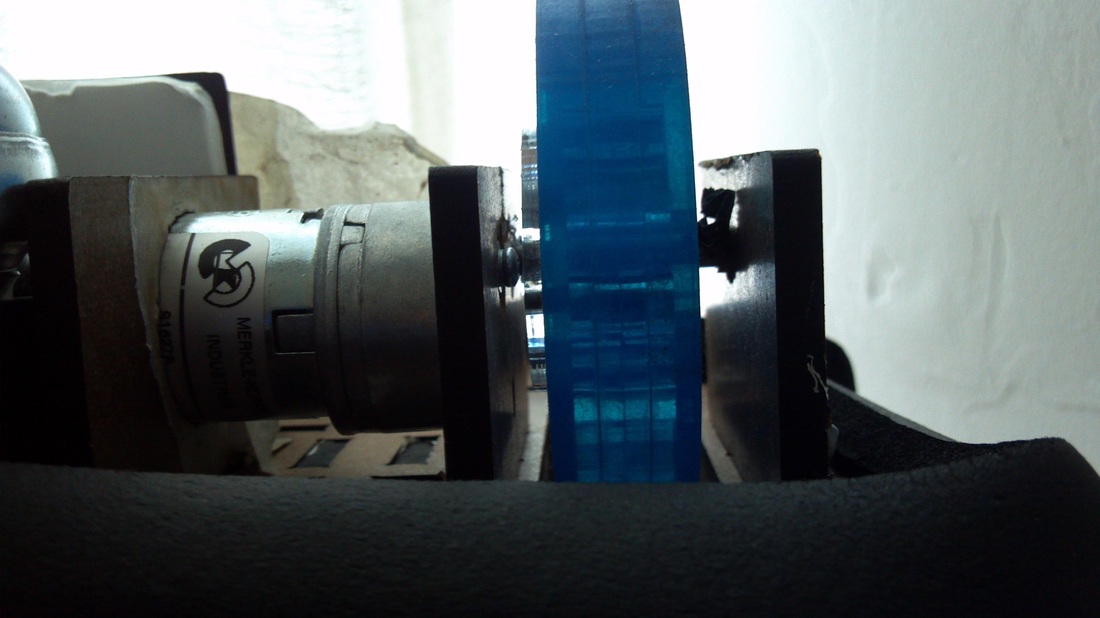
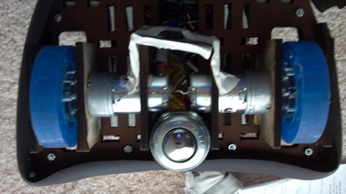
Motor Mounts and shaft coupling
Our motors had a 3/16" shaft with a flat on one side. In order to couple to the motor, the first layer of acrylic in the hub of wheels had a hole cut in the same shape. This was pressfit onto the motor shaft. This layer then coupled to the rest of the wheel hub by way of 1/8" pins and 3 4-40 screws. A 3/6 pin was then press fit into the rest of the wheel which extended outward to interface with a shaft mount. Three pieces of duron were cut to fit around the body of the motor, the shafts. The one that was placed on the face of the motor also had holes to enable 3 4-40 screws to be inserted through the duron and into threaded holes on the face of the motor. Brass bushings were inserted into the supporting pieces of Duron in order to reduce friction. Several pictures of the wheels and motor mounts are included below.