Beacon Sensing Circuit
Project specifications
During the project we were given the task of distinguishing between 2 different signals:
1) the 4 kHz signal given off by the sequester
2) the 850 Hz signal from the beacons (placed on top of each robot)
1) the 4 kHz signal given off by the sequester
2) the 850 Hz signal from the beacons (placed on top of each robot)
Initial ideas and tests
Our initial plan was to take in the signal using a LTR-3208E IR photo-transistor and filter out the signals in hardware.
To quickly set up the system we initially attached the phototransistor to a LM324 op-amp in a non inverting amplifier configuration with at a gain of 10. When a beacon was in front of the phototransitor, we could see the oscillating square wave signal on an oscilloscope. The next step was to filter out extraneous signals such as sunlight. We used a high pass filter to block out the signals which would had very low frequencies such as solar radiation. However, what we discovered was that our signal seen had a voltage offset. The problem with the DC offset was that if we wanted to amplify the signal of interest, we would subsequently amplify the offset as well. This would limit our signal amplification and we address this issue during our final circuit implementation.
Besides the offset, we devoted a large amount of time trying to differentiate between the 850 Hz and 4 kHz signal. We initially tried using a Low-Pass filter to attenuate any signal above 850 Hz. However, what we discovered was that we would not be able to significantly attenuate the 4 kHz signal using a first order filter. We soon found ourselves deep into searching through mulitstage filters, such as Sallen-Key filters, and other methods in hardware that would essentially increase the steepness of the roll-off transition region in the Bode plots. Before going down the rabbit hole and spending too much time in developing these active filter topologies, we started looking into a software solution to this problem
Software Solution
Since we were given an Arduino Uno, we looked for ways to input our signals from the photo-transistor and in software differentiate between the 850 Hz and 4 kHz signals. What we discovered was that the Arduino had a hardware announcement system which notifies a program when an event has occurred without having to constantly check the state of a bit. This is the interrupt function (http://arduino.cc/en/Reference/Interrupts). We discovered that interrupts could be a powerful tool for us as we could implement the interrupts into our code without having to devote too much computation in the beacon sensor. In order to utilize the interrupts, changes in signal states such as rising and falling edges trigger responses our program can define (this will be discussed below).
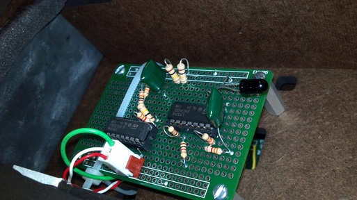
Beacon sensing circuit mounted on the top level of the chassis
Final Beacon Implementation
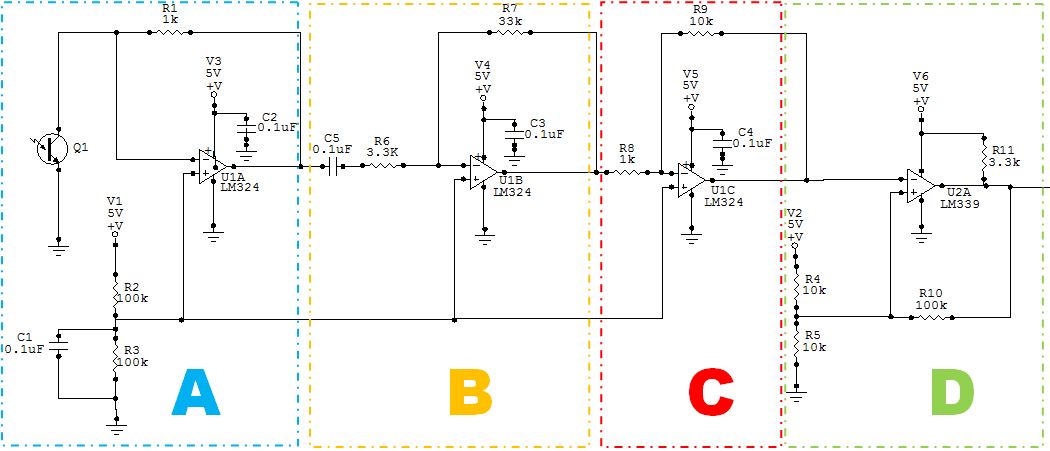
A. The IR photo-transistor is placed in an inverting amplifier circuit. The voltage divider attached to the non-inverting input of the op-amp acts as a rail-splitter. This sets the output voltage of A. centered around 2.5V. C1 in our voltage reference essentially creates a low-pass filter that help minimize disturbances on V1.
B. We then pass the signal from A into a High-Pass filter with corner frequency (using C5 and R6) of 482 Hz. To address our DC offset, C5 acts as a AC coupling capacitor which blocks DC signals while passing on AC signals. Based on the inverting amplifier configuration, there is a 10 x gain of the signal.
C. To further amplify our signal, we sent the signal out of B through a inverting amplifier in C, with another 10 x gain.
D. To translate the analog signal into a digital one which would be passed on to the Arduino, we created a Schmitt trigger. The Schmitt trigger high voltage reference was 2.619V and the low voltage reference was 2.38V
Our circuit worked very well in detecting the 850 Hz and 4 kHz signals throughout the whole length of the arena (8 feet).
Once the digital signal was passed to the Arduino we used interrupts to create a frequency counter. Here are some of the features we discovered about the interrupts as well as our software implementation:
-Arduino Uno has 2 external interrupts (pins 2 and 3)
-Using the syntax attachInterrupt(interrupt, function, mode), we attached our circuit (above) to pin 2 of the Arduino and created a frequency counter function which would trigger when the signal changed from low to high (RISING).
-To ensure we kept the proper frequency and timer count, we detached the Interrupt every time the frequency was calculated.
Conclusions:
Overall, this implementation worked very well for our robot. The function above allowed us to read the frequency values of the 850 Hz and 4 kHz values. This let us isolate the 850 Hz signal of interest and integrate this newly found skill into our state machine.
The issues we ran into with this implementation included:
-if the 850 Hz and 4 kHz beacons were placed next to each other, the signals would overlap giving a frequency count reading of ~2000-3000 Hz.
-the interrupt sampling time was very important to get an accurate frequency reading, thus playing around with the TIME_INTERVAL (see attached code) value gave us different frequency values. If the TIME_INTERVAL was very small ~10 (meaning we calculate the frequency count every 10 milliseconds) we would get incorrect readings as we may miss counting some rising signal changes in that small window. If the TIME_INTERVAL was large ~1000 (meaning we calculate the frequency every 1 second), this would give us very accurate readings but this would limit the number of times we could read a frequency value (which directly influences our robot's behavior).
To overcome these issues we created threshold values around our signals of interest such as:
if frequency < 600 Hz do A.
else if frequency >601 & frequency < 1000 Hz do B.
etc.
We also discovered that calculating the frequency every 100 milliseconds gave us a fairly accurate reading while providing us a quick response time to adjust our robot's behavior to the frequency readings. For the scope of the project, our beacon sensing worked well. However, with more time and resources, we would have liked to have added more sensors to give our robot directionality.
| irbeaconsensor_v2.ino |
