Tape Sensing Subsystem
Requirement for our tape sensing subsystem was to distinguish between two cases, robot on white reflective background and robot on black tape.
Tape sensing circuit:
Our tape sensing circuit consists of three parts, an oscillator part using one LM555, a sensing part using one OPB704, and a signal processing part using one LM324.
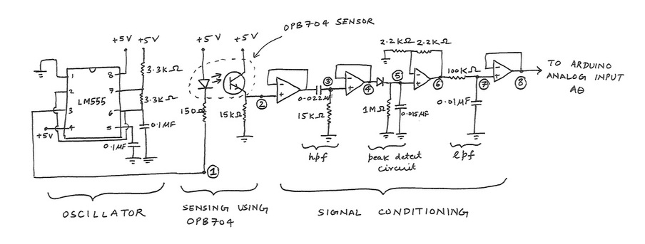
- Oscillator: The oscillator part takes care of filtering out any background IR (such as changing sunlight through out the day) by providing a square wave of known frequency (~1.5kHz in our circuit). Referring to figure, at point 1 the voltage oscillates between 0 and 5 volts with a frequency of ~1.5kHz.
- Sensing using OPB704: The output of oscillator at point 1 connects to the infrared emitting LED of the OPB704 sensor with a 150 ohm resistor. The resistor is sized such that we get ~20 mAmp current through LED when voltage is 0.0 V at point 1. The LED does not emit any IR when voltage at point 1 is 5.0 V. If white reflective background is present the IR emitted from LED reflects back to photo-transistor of OPB704; if black tape is present under the sensor very little amount of IR gets reflected back towards photo-transistor. The photo-transistor output at point 2 oscillates between 0.0 V and ~4.0 V at the oscillator frequency when sensor sees white background. When sensor sees black tape the output at point 2 oscillates between 0.0 V and ~0.3 V.
- Signal conditioning of tape sensor output: The output of photo-transistor at point 2 is buffered through an op-amp (LM324) and its out put is filtered using a high pass filter of frequency 400Hz. This high pass filter filters down any 60Hz electrical noise coming out due to presence of electric lighting. The output of hpf at point 3 is passed through an op-amp (LM324) to buffer it. The output of the op-amp at point 4 is passed through a peak detect circuit that consists of a diode and an RC circuit. The diode passes current only when the sensor OPB704 is on a white reflective background. The output of diode connects to a RC filter which discharges the peak detect circuit with a time constant of 0.015 seconds. This time constant ensures that when the robot moves from white to black the capacitor discharges quickly. This capacitor also charges quickly when robot moves from black to white and remains charged despite having an oscillatory signal (due to LM555) at point 4. The output at point 5 remains a nearly constant value (DC) of 2.0 V when sensor OPB704 sees a white reflective background, this output drops to < 0.1 V when sensor sees a black tape. The output at point 5 is amplified by a factor or 2 using an op-amp (LM324). The output of op-amp at point 6 is passed through a low pass pass filter of corner frequency 160Hz. This low pass filter filters out any very high frequency noise coming in the signal due to any EMI, etc. The output of low pass filter at point 7 is buffered through an op-amp (LM324) before it is passed on to Arduino analog input. The voltage level at point 8 remains nearly constant at ~4.0 V when sensor sees a white reflective background, this voltage drops to < 0.1 V when the sensor sees a black background.
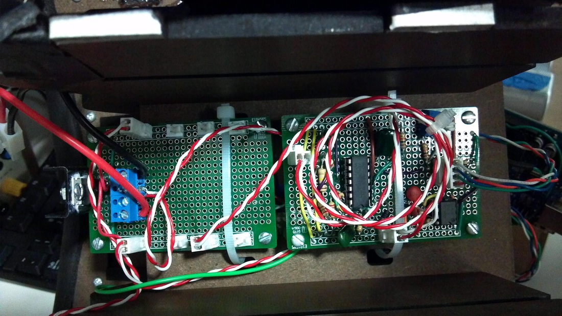
The final tape sensing circuit can be seen on the right of this photo.
Software for testing the tape-sensing circuit
The following Arduino code was used to test the tape sensing circuit.
| tape_sense_circuit_tester.ino |
